Big Button - Part 3 - Programming Hardware Components
Table of Contents
Introduction
💻 HACKER In this post, we will go over the general tools, hardware, and components needed for the programming hardware parts for this project.
TIP
If you are unfamiliar with any of these tools or components, a quick google search or a AI chat prompt on any of these tools and components will get you going on how to fundamentally use them.

Overview
Tools
The following is an overview of all the things needed. Further down in this post, you can read about the details for each item.
| Name | Purpose | Online Link |
|---|---|---|
| Soldering Station | For soldering wires and components | Link |
| Wire Cutter/Stripper | For cutting and stripping small gauge wire | Link |
| Multimeter | For measuring voltage, current, and resistance | Link |
Components
| Name | Purpose | Online Link |
|---|---|---|
| Raspberry Pi Pico 2 W | Main microcontroller for the project | Link |
| Pico Debug Probe | For connecting to Pico for debugging | Link |
| Pico Breakout Board (Dev) | For easy access to Pico pins during development | Link |
| Buzzer | For audio feedback | Link |
| Wire Assortment | For wiring components | Link |
Tools
Soldering Station
This project will require some soldering of various components such as wires and terminals. There are many different soldering tools with a variety of quality and use-case.
The soldering station that I am working with and that I recommend for beginners is an all-in-one soldering station kit shown below and available on Amazon here.
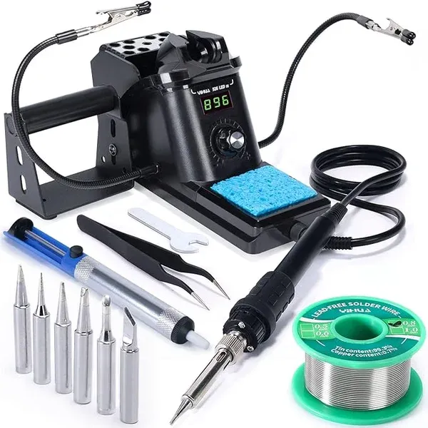
Here we have everything from helping hands to solder to solder sucker for de-soldering and cleanup.
Wire Tools
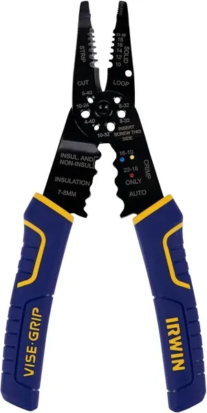
Building anything electrical will require work with wires. Specifically, for our low current and low voltage applications we will be using small wire gauges.
Wire strippers are often the same tool as wire cutters. Again, as a casual hobbiest, I would not necessarily recommend the top shelf tools, here a regular wire cutter/stripper is just fine.
Multimeter
Often times we will need to test if two things are soldered correctly, connected right, or give us some voltage at some point and time. In these types of situations (and more), a multimeter comes in very handy.
A multimeter measures multiple electrical properties: voltage, resistance, and current. It is one of the most basic and most useful electrical tools you can get familiar with. Here is a quick overview video on how to use a multimeter.
Luckily, for the vast majority of hobbiest use-cases, a regular grade multimeter is just fine, not very expensive, and highly available.
I recommend selecting a multimeter with a good set of probe features and clamps, a good display, and a kick stand. Maybe something like this one.

Components
Raspberry Pi Pico 2 W
The Raspberry Pi Pico 2 W (RPi Pico 2 W) microcontroller will be our central brain for this project. All logic will live on this microcontroller.
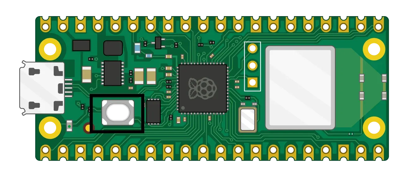
This Raspberry Pi is powered by an arm-based
RP2350 chip (the RP2040
is for the RPi Pico 1), while having other on-board peripherals
such as a wireless module (the W in the name), a bluetooth chip, temperature sensor, and more.
NOTE
You are free to use the Raspberry Pi Pico 1 with the RP2040 chip, however the upcoming code will have to be modified. Although, coding on the RP2040 chip is “easier”, the faster and more powerful RP2350 is designed to be more of a industry standard and applicable for a more variety of situations.
See the official Raspberry Pi Pico documentation for more information.
TIP
You will have to connect a debug module (see next section) to the RPi. The debug module connects to the RPi Pico via 3 debug pins. I would recommend buying the RPi pico with pins already pre-soldered.
The Raspberry Pi Pico 2 W is obviously not the only popular microcontroller of its kind. You could select a different microcontroller that fits a specific need or skill set. For example, the Freenove ESP32-WROOM Board is also not a bad choice, however in scope of our project we will stick to the Raspberry Pi.
Raspberry Pi Pico Debug Probe
When programming and developing on a microcontroller, it is crucial that you know what is happening on the microcontroller when it is running. That is, when connecting your computer to the microcontroller you are able to actively view code deployment logs, runtime logging messages, error messages, and other connection-related messages.
Typically microcontollers provide a debug probe/module that accomplishes just that. Our debug probe will connect via UART serial port via the 3 pins (TX, GND, RX) specially designated to it on the Raspberry Pi Pico and located next to the large wireless module.
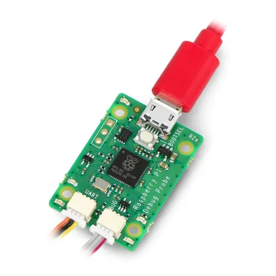
See the official Raspberry Pi Debug Probe documentation for more information.
NOTE
There is a way to achieve this same function but without a Raspberry Pi debug probe. This involves a second Raspberry Pi Pico connected to your main one. Here is more information about it. However, to gain simplicity by sacrificing cost we are sticking to the official debug probe provided for the Raspberry Pi.
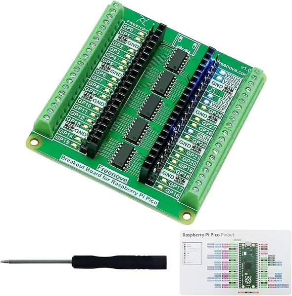
Raspberry Pi Pico Breakout Board for Development
For development and for actual final implementation of our Raspberry Pi Pico 2 W, we will use breakout boards. A breakout board will take these pins and “break them out” onto a separate circuit board. That is, it maps the inputs and outputs of our Raspberry Pi Pico W onto easily accessible connectors.
During programming and troubleshooting we will utilize a more complete breakout board. This breakout board includes LEDs for pin inputs and outputs, more ground connectors, clear labels, and more. We will use this breakout board during initial programming, testing, and iterations. (Online Link)
NOTE
Here lots of tutorials and manuals may use a electrical breadboard, plugging wires and components like LEDs and buttons into the bread board. This acceptable, however to simplify things and quickly get going we will use this development board that has on-board LEDs. For buttons, for now, we will simulate a button press by simply touch two wires together.
Wire Assortment
Last but not least. Any electrical project of this type will need wire. In our case, this assortment provides us with a small gauge wire in different colors. Online Link It will be slighly more than we will be using for our programming setup, however this wire will be used in later fabrication steps as well.
Alright! … Now that we have that out of the way, let’s move forward!No spam. Unsubscribe any time.