Big Button - Part 4 - Connecting Programming Hardware
Table of Contents
- Introduction
- Hardware Needed
- Soldering Header Pins
- Breakout Board
- Connecting the Debug Probe
- References
Introduction
💻 HACKER The goal of this part is to connect all of the hardware needed to start programming. We will lay out all needed hardware, carefully explain each, and show how each connects.
Hardware Needed
- A computer running Linux, MacOS, or Windows
- Raspberry Pi Pico 2 W
- Raspberry Pi Pico Debug Probe
- Raspberry Pi Pico Breakout Board - For Development and Testing
NOTE
Remember, all items needed for this entire project are listed in the previous part.
Soldering Header Pins
Before we can connect the debug probe to the Raspberry Pi Pico 2 W, we will have to ensure that the Pico has 3 header pins soldered onto its debug pin output as shown below. The debug probe will connect to these 3 header pins.
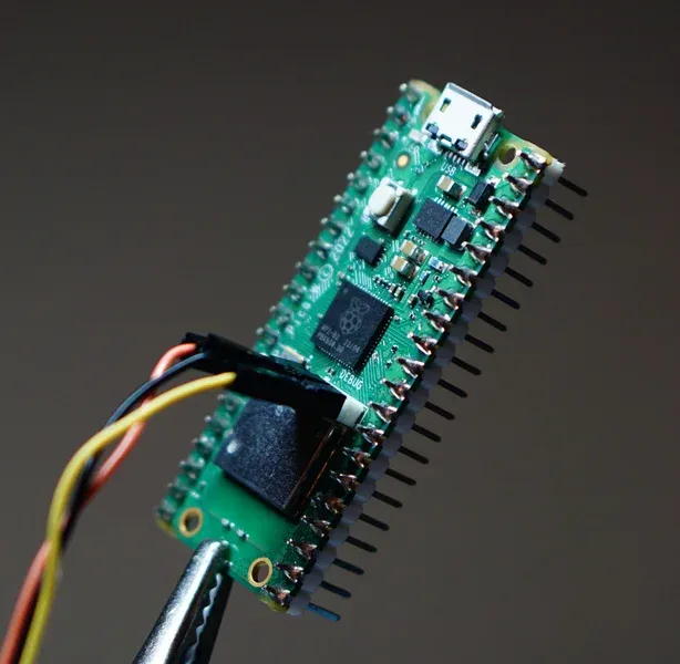
Your Raspberry Pi Pico W should come with the header pin included. However, if you do not have it, you can order it here.
Before soldering the header pins into place, ensure they are positioned correctly. While there are a variety different ways to set this up, given the suggested soldering station from the previous part, here is an option to do that.
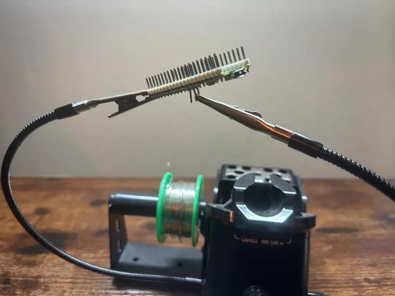
Next solder the 3 header pins onto the Pico. For reference here is a great soldering tutorial to get you started on how to solder header pins in general.
WARNING
If you have not soldered before, please be very careful with a hot soldering iron. Please use all necessary safety precautions. In addition, feel free to test your soldering skills on something else before soldering your Raspberry Pi.
Breakout Board
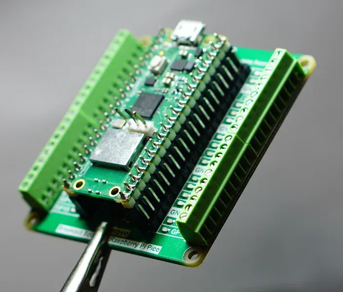
Let’s place the Raspberry Pi Pico 2 W into the breakout board. Orient the Pico the correct way, carefully place all of the Pico’s pins into the breakout board’s connectors, and gently and evenly press the Pico into the breakout board.
Connecting the Debug Probe
Now that we have all pieces ready, we are able to connect the debug probe. The debug probe should come with a USB cable and a cable that connects its JST-SH connector to a female 3-pin connector (see here).
We will first connect the debug probe module to the Raspberry Pi Pico 2 W header pins we soldered in the previous section. As we are connecting the header pins, we will be looking at the Pico from the top, where the Pico’s USB connection is on top.
The pins are connected as follows:
- Pin 1 - Left Pin - Orange - Serial Data (TX)
- Pin 2 - Middle Pin - Black - Ground (GND)
- Pin 3 - Right Pin - Yellow - Serial Clock (RX)
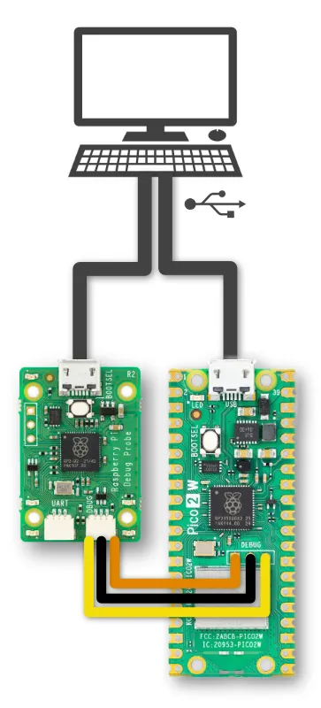
NOTE
On the debug probe, we are only connecting the DAP (Debug Adapter Protocol)
(marked as D) connection and not the Serial UART connection (marked as U).
We will be not be using the serial UART wire to upload anything to the Pico.
Next, connect the debug probe and also the Raspberry Pi Pico 2 W to your computer’s USB port. Note that you will obviously need two open USB A ports on your computer. However, you may want to use some kind of USB hub in order to combine these into one single USB input or into a USB C port.
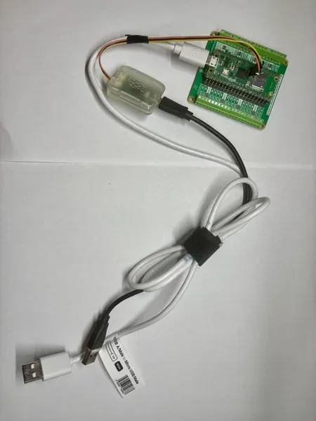
Below is the entire setup. Note that I am using a small piece of tape between the debug probe cable and the Raspberry Pi Pico 2 W USB output. Also, for better handling, there is a tie to tie together the USB cables.
NOTE
Remember, instead of using the debug probe we could also use a second Raspberry Pi Pico
that connects to our main Pico and the computer. More information can be found here.
This effectively loads up the debugprobe firmware
onto the second Pico.
References
- Raspberry Pi Pico 2 W
- Raspberry Pi Debug Probe
- Raspberry Pi Debug Probe Testing
- Breakout Board For Raspberry Pi Pico
- Soldering header pins onto Pico
OK! On to check if this thing even works …
No spam. Unsubscribe any time.