Big Button - Part 13 - Configuring System Clocks and Performance
Table of Contents
Introduction
💻 HACKER OK, you are probably pretty tired of configurations and settings! However, this part is the final and critical piece in configuring our embedded device before we add any substantial functional logic and code.
In this part, we will learn about and configure microcontroller clocks. That is, we will set how fast sub-systems in the microcontroller process information. For instance, we can set the CPU speed or even USB communication speed.

For some embedded projects, the default clock settings may be just fine. However, setting clock speeds can become very useful and offer great control for certain situations. For example, a microcontroller tasked with music/audio processing will need to be timed differently compared a device simply monitoring room temperature.
Note that here when we describe clock “speed”, we are describing the clock frequency - the number of events per second. Each clocks here are measured in Hertz, cycles per second (i.e. 130 MHz = 130,000,000 Hertz = 130,000,000 cycles per second).
Clock Frequency Generation
Let’s discuss how we can generate different frequencies for different parts of the system.
NOTE
We are just trying to learn how things generally come together and are eventually applied. How exactly the microcontroller produces a variety of frequencies is a whole science on its own! The limits and nuances are beyond the scope of this tutorial.
Different parts of your microcontroller need different speeds. The CPU wants to run fast (125+ MHz), USB needs exactly 48 MHz, and the real-time clock barely ticks along at 47 kHz. How does one chip create all these different frequencies?
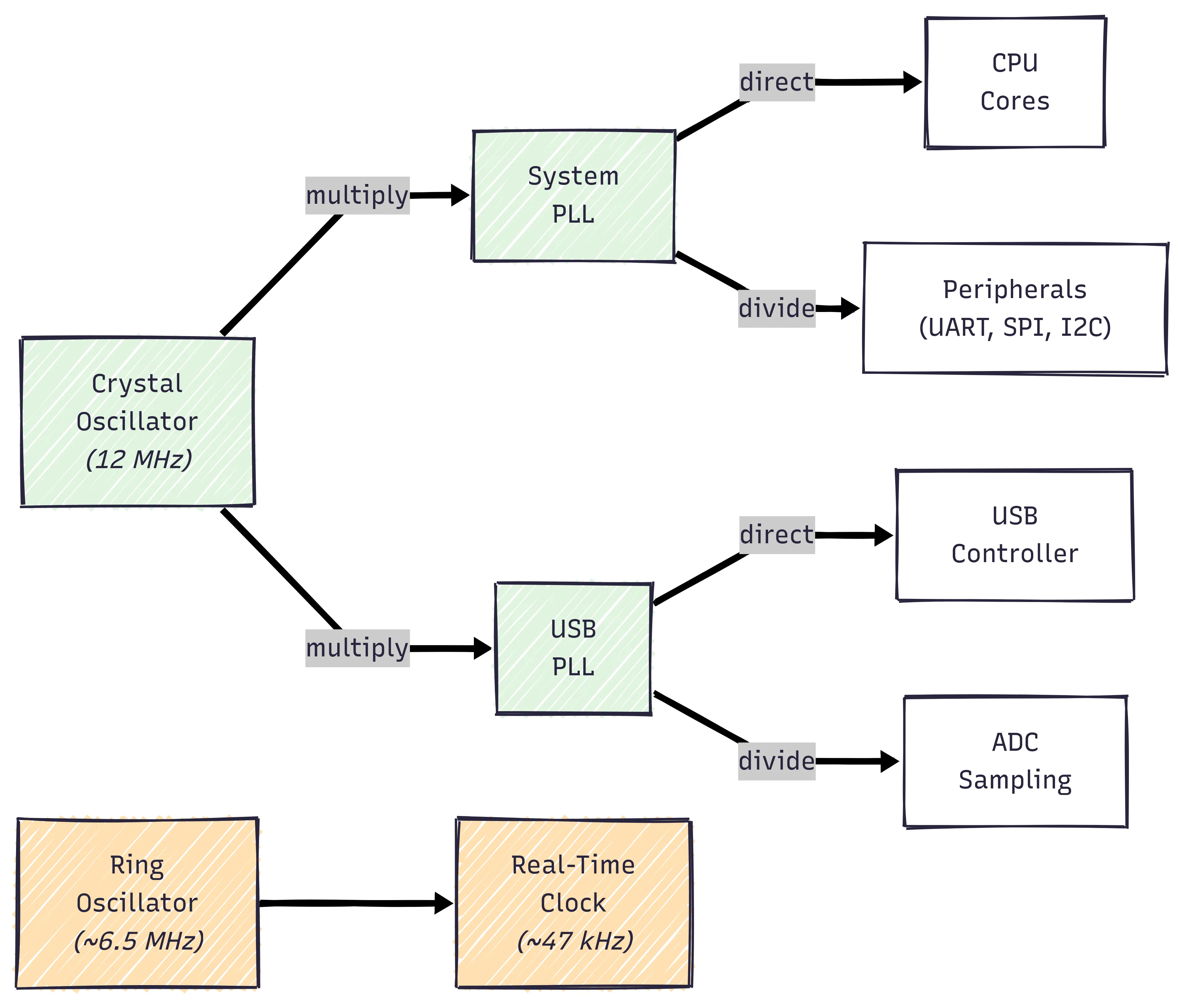
At the very heart, the RP2350 has two primary clock sources:
-
Crystal Oscillator (XOSC) - A 12 MHz quartz crystal that provides extremely stable timing. This external crystal physically vibrates 12 million times per second. It is used for normal operation because of its speed and stability.
-
Ring Oscillator (ROSC) - An internal ~6.5 MHz ring oscillator built from transistors. It’s less accurate but doesn’t need external components and uses less power.
To get from 12 MHz quartz crystal frequency to 125+ MHz, we use multiple Phase-Locked Loops (PLLs):
-
System PLL: Multiplies the 12 MHz crystal up to 125-150 MHz. The CPU uses this directly, while peripherals (UART, I2C, etc.) can divide it down as needed.
-
USB PLL: Multiplies the 12 MHz crystal up to exactly 48 MHz. USB uses this directly, while the ADC can divide it down for slower sampling rates.
Think of a PLL as a frequency multiplier that stays perfectly synchronized with the crystal’s stable timing.
The diagram below shows how clock generation flows through the Pico’s RP2350.
Clocks ⏰
Now that we see how the different clocks are generated and relate to each other, let’s explain each clock in a little more detail.
System CPU Clock
The system CPU clock drives the ARM Cortex-M33 processor cores and most peripherals including UART, SPI, I2C, PWM, and PIO. This is the primary clock that determines how fast your code executes.
Common frequencies and their characteristics for this chip:
| Frequency | Notes |
|---|---|
| 48 MHz | Minimum for USB operation; maximum power savings |
| 64 MHz | Good balance for battery-powered applications |
| 96 MHz | Moderate performance with lower power draw |
| 125 MHz | Default - Recommended for most applications |
| 133 MHz | Standard overclock; stable on most chips |
| 150 MHz | Maximum official - Highest performance |
The CPU clock directly affects instruction execution speed and peripheral timing.
CPU Clock Trade-offs
Setting the CPU clock frequency typically involves balancing three factors:
- Performance - Higher speed = faster code execution
- Power Consumption - Higher speed = shorter battery life
- Temperature - Higher speed = more heat generated
For example, the RP2350 at 150 MHz uses ~30% more power than at 125 MHz. Dropping to 64 MHz can cut power consumption by 40-70% but doubles execution time.
| Clock Speed | Performance | Power Draw | Best For |
|---|---|---|---|
| 48-64 MHz | Slow | Low | Battery-powered sensors (underclocking) |
| 125 MHz | Default | Moderate | General purpose |
| 150 MHz | Fast | High | Compute-intensive tasks (overclocking) |
NOTE
Additional factors to consider: peripheral timing requirements, EMI emissions, and wake-up latency from sleep modes.
The Raspberry Pi Pico 2 W is shipped with some default clock frequencies, however in our design we will change clock values.
Peripheral Clock
The peripheral clock drives UART, SPI, I2C, PWM, and PIO state machines. It’s derived directly from the system clock and can optionally be divided down.
For example, dividing by 1 will make it run at full speed, dividing by 2 will run the peripherals at half speed.
USB Clock
The USB clock must run at exactly 48 MHz to comply with USB 2.0 specifications. This is a hard requirement. USB communication will fail at any other frequency. However, if this system is not needed, power could be saved by turning this clock off.
Analog-Digital (ADC) Clock
The ADC clock controls how fast the analog-to-digital converter samples analog voltages. Slower sampling can improve accuracy by allowing more settling time.
Faster clocks (48 MHz) give quick conversions but more noise. Slower clocks (1-10 MHz) reduce noise but limit sample rate. Choose based on whether you need speed or accuracy.
Real-Time Clock (RTC)
The RTC provides low-power timekeeping, typically running even when the main system is in deep sleep. It counts seconds, maintains time/date, and can wake the system.
The RTC always runs and is used for scheduled wake-ups, timestamping events, and maintaining time during sleep. Remember, this can lose time when power is removed unless you add a backup battery.
File Changes
Phewww… So much “theory”. Let’s get back to work and make some changes to our project …
For a quick indicator of what files we will add or change in this part, expand the following file tree.
17 collapsed lines
.├── build.rs # <--- Changes├── .cargo│ └── config.toml├── Cargo.lock├── Cargo.toml├── configs.json # <--- Changes├── .gitignore├── memory.x├── README.md # <--- Changes├── .rustfmt.toml├── rust-toolchain.toml├── secrets.json└── src ├── clocks_config.rs # <--- New ├── main.rs # <--- Changes └── utility.rsconfigs.json
Let’s first define the configuration constants that will be used to define the clock frequencies. This entire file will replace the pre-existing sample constant we had there before.
By the above explanations, and by the configuration constant name, it should be relatively obvious what each constant will be used for.
{ "clock_system_frequency_mhz": "133", "clock_usb_frequency_mhz": "48", "clock_peripheral_divider": "1", "clock_adc_frequency_mhz": "48", "clock_reference_divider": "1"}build.rs
Next, as before, we must ensure that our configuration constants are being injected and loaded into our running program during the program build process.
/// Main build script entry pointfn main() {15 collapsed lines
// Put `memory.x` in our output directory let out_dir = &PathBuf::from(env::var_os("OUT_DIR").unwrap()); fs::File::create(out_dir.join("memory.x")) .unwrap() .write_all(include_bytes!("memory.x")) .unwrap();
// Ensure 'memory.x' is on the linker search path println!("cargo:rustc-link-search={}", out_dir.display());
// Re-run for any changes to the following files println!("cargo:rerun-if-changed=build.rs"); println!("cargo:rerun-if-changed=memory.x"); println!("cargo:rerun-if-changed=configs.json"); println!("cargo:rerun-if-changed=secrets.json");
// Load configurations from local 'configs.json' file let configs_keys = [ "clock_system_frequency_mhz", "clock_usb_frequency_mhz", "clock_peripheral_divider", "clock_adc_frequency_mhz", "clock_reference_divider", ]; load_configs(out_dir.to_str().unwrap(), configs_keys).unwrap_or_else(|error| panic!("[ERROR] {error:?}"));
// Load secrets from local 'secrets.json' file with XOR obfuscation let secrets_keys = ["super_secret_info"]; load_secrets(out_dir.to_str().unwrap(), secrets_keys).unwrap_or_else(|error| panic!("[ERROR] {error:?}"));}
6 collapsed lines
/// Loads configuration values from configs.json and generates a configs.rs file/// with Rust constants for use in the embedded application////// # Arguments/// * `out_dir` - The target build directory path/// * `config_keys` - Array of configuration keys to extract from configs.jsonfn load_configs(out_dir: &str, config_keys: [&str; 5]) -> io::Result<()> { // ....}
// ....src/clocks_config.rs
This is a newly added Rust file that will solely be used for anything system
clock related. We can obviously add all this code into main.rs, however
let’s stay organized.
We will add code part-by-part, while explaining our addition. However, please make sure to also review the code and read the code comments!
To start off, we will add all the dependencies we will use within this file.
This includes embassy_rp HAL
modules that give us the ability to set system and USB clock configurations.
We are also adding a ClockSettings configuration struct to easily pass
clock settings.
//! Raspberry Pi Pico 2 W RP2350 clock/PLL setup//! Functions to set, verify, and log effective system clock frequencies
use embassy_rp::clocks::{self, ClockConfig, PllConfig, SysClkConfig, SysClkSrc, UsbClkConfig, UsbClkSrc, XoscConfig};use embassy_rp::clocks::{AdcClkConfig, AdcClkSrc, PeriClkSrc, RefClkConfig, RefClkSrc};use embassy_rp::config::Config as HalConfig;use embassy_time::{Instant, Timer};
use defmt::*;use defmt_rtt as _;use panic_probe as _;
/// Clock configuration structure to hold all clock settings for RP2350pub struct ClockSettings { pub xosc_crystal_hz: u32, pub system_frequency_mhz: u32, pub usb_frequency_mhz: u32, pub peripheral_clock_divider: u8, pub adc_frequency_mhz: u32, pub reference_clock_divider: u8,}In the following code addition to this file, we are adding a function that figures out our PLL configurations. That is, given some reference clock (XOSC), we want to configure the PLL. We will be using this function to configure the System PLL and also the USB PLL.
Note the way the PLL configuration constants for PLLConfig
are defined. If you are interested in how these values are derived, check out
the official RP2350 datasheet
and also this article.
// ....
/// Calculate the PLL (Phase-Locked Loop) configuration for the system clock and USB clock////// * `desired_freq_mhz` - Desired frequency in MHz/// * `xosc_freq_hz` - Crystal oscillator frequency in Hz/// * `post_div1` - Post divider 1 value/// * `post_div2` - Post divider 2 value////// The formula for calculating the PLL configuration is:/// `fbdiv = (desired_freq_mhz * post_div1 * post_div2) / xosc_freq_mhz`pub fn calculate_pll_config(desired_freq_mhz: u32, xosc_freq_hz: u32, post_div1: u8, post_div2: u8) -> PllConfig { const HZ_PER_MHZ: u32 = 1_000_000;
let refdiv = 1u8; // Fixed reference divider let xosc_freq_mhz = xosc_freq_hz / HZ_PER_MHZ;
// VCO target frequency in MHz (desired output * post dividers) let vco_target_mhz = desired_freq_mhz * post_div1 as u32 * post_div2 as u32;
// Feedback divider: how many times to multiply the reference to hit the VCO target let fbdiv = vco_target_mhz / xosc_freq_mhz;
debug!( "PLL Config: {} MHz -> refdiv={}, fbdiv={}, post_div1={}, post_div2={}", desired_freq_mhz, refdiv, fbdiv, post_div1, post_div2 );
PllConfig { refdiv, fbdiv: fbdiv as u16, post_div1, post_div2, }}The next function will configure all of the clocks we want to configure that are shown in the diagram above.
With our PLL configurations defined, we are setting the XOSC configurations. Now we are free to configure all of the downstream clocks: system, usb, peripheral, ADC, RTC.
At the very end of this function we are returning all of our configurations back to
the main program. Remember, here we are only setting up configurations, the actual
implementation of these configurations will eventually happen within main.rs
// ....
/// Configure all system clocks for RP2350////// This function configures:/// - System PLL and clock/// - USB PLL and clock/// - Peripheral clock source/// - ADC clock/// - Reference clockpub fn configure_all_clocks(hal_configuration: &mut HalConfig, settings: ClockSettings) -> &mut HalConfig { // Calculate the PLL configuration for the system clock and USB clock let sys_pll_config = calculate_pll_config(settings.system_frequency_mhz, settings.xosc_crystal_hz, 6, 2); let usb_pll_config = calculate_pll_config(settings.usb_frequency_mhz, settings.xosc_crystal_hz, 6, 5);
// Create and configure the external oscillator (XOSC) settings let mut clocks = ClockConfig::crystal(settings.xosc_crystal_hz); clocks.xosc = Some(XoscConfig { hz: settings.xosc_crystal_hz, // Set XOSC frequency sys_pll: Some(sys_pll_config), // System PLL configuration usb_pll: Some(usb_pll_config), // USB PLL configuration delay_multiplier: 128, // Used to calculate the startup delay (in cycles) for the crystal oscillator });
// Configure the system clock settings clocks.sys_clk = SysClkConfig { src: SysClkSrc::PllSys, // Set system clock source to system PLL div_int: 1, // No division div_frac: 0, // No fractional division };
// Configure the USB clock settings clocks.usb_clk = Some(UsbClkConfig { src: UsbClkSrc::PllUsb, // Set USB clock source to USB PLL div: 1, // No division phase: 0, // No phase shift });
// Configure the peripheral clock source // RP2350 uses peri_clk_src field clocks.peri_clk_src = Some(match settings.peripheral_clock_divider { 1 => PeriClkSrc::Sys, // Use system clock directly _ => { debug!("[NOTE] Peripheral clock divider is applied at runtime, not in clock config"); PeriClkSrc::Sys // Still use system clock } });
// Configure the ADC clock // ADC clock can be sourced from USB PLL for stable 48MHz operation clocks.adc_clk = Some(AdcClkConfig { src: AdcClkSrc::PllUsb, // Source from USB PLL (48MHz) div: (settings.usb_frequency_mhz / settings.adc_frequency_mhz) as u8, // Calculate divider phase: 0, // No phase shift });
// Configure the reference clock // Reference clock is typically used for watchdog and timers clocks.ref_clk = RefClkConfig { src: RefClkSrc::Xosc, // Source from crystal oscillator div: settings.reference_clock_divider, // Apply configured divider };
hal_configuration.clocks = clocks; hal_configuration}Those were the most critical pieces to this file. However, let’s add a few more things for utility and convenience. This will be time well spent in the long run!
It would be nice to be able to verify if the system CPU clock has deviated from our defined settings. To do this we are adding a function that will wait for a specified number of milliseconds, and then compare the actual measured elapsed time versus the expected elapsed time.
We will use this right after setting our device clocks.
// ....
/// Verify the system clock frequency using a timer////// * `milliseconds` - Duration in milliseconds to wait before measuring the system clockpub async fn verify_clock_with_timer(milliseconds: u64) { let start = Instant::now(); // Start timer Timer::after_millis(milliseconds).await; // Wait for the specified duration let measured_elapsed = start.elapsed().as_micros(); // Stop timer let expected_elapsed = milliseconds * 1000;
debug!( "[System clock frequency test] Actual: {} microseconds -> Measured: {} microseconds", expected_elapsed, measured_elapsed );
// Calculate and print the clock accuracy percentage let measured_diff = (measured_elapsed as i64 - expected_elapsed as i64).abs();
// Use u64 to prevent overflow in calculation let accuracy_percent_int = ((measured_diff as u64 * 100) / expected_elapsed as u64) as u32; let accuracy_percent_frac = ((measured_diff as u64 * 10000) / expected_elapsed as u64 % 100) as u32;
debug!( "[System clock frequency test] Clock accuracy: {}.{:02}% off", accuracy_percent_int, accuracy_percent_frac );}The next thing here is simply a summary of our clock settings. Such an outline within the terminal is great to have showing at the beginning of the program for any type of troubleshooting.
We will also use it right after setting our device clocks.
// ....
/// Display device clock frequencies with enhanced detailpub fn print_device_frequencies() { debug!("Log Device Clock Frequencies:"); debug!("[Oscillators]"); debug!(" - ROSC (Ring Oscillator): {} Hz", clocks::rosc_freq()); debug!(" - XOSC (Crystal Oscillator): {} Hz", clocks::xosc_freq());
debug!("[PLLs (Phase-Locked Loops)]"); debug!(" - SYS PLL: {} Hz", clocks::pll_sys_freq()); debug!(" - USB PLL: {} Hz", clocks::pll_usb_freq());
debug!("[System Clocks]"); debug!(" - SYS CLK (System Clock): {} Hz", clocks::clk_sys_freq()); debug!(" - REF CLK (Reference Clock): {} Hz", clocks::clk_ref_freq()); debug!(" - PERI CLK (Peripheral Clock): {} Hz", clocks::clk_peri_freq());
debug!("[Specialized Clocks]"); debug!(" - USB CLK (USB Clock): {} Hz", clocks::clk_usb_freq()); debug!(" - ADC CLK (ADC Clock): {} Hz", clocks::clk_adc_freq());}src/main.rs
Now that our clock configuration code is in place, we can use it within our main program.
Starting off, we will reference our general Embassy HAL configurations as HalConfig.
This is super minor, however will cause less confusion in later code additions.
Then we import our clock_config.rs code that holds the functions we just wrote in the
previous section.
4 collapsed lines
#![no_std]#![no_main]#![allow(unused_variables)] // only used for development#![allow(unused_imports)] // only used for development
use defmt::*;use defmt_rtt as _;use panic_probe as _;
use embassy_executor::Spawner;use embassy_rp::config::Config as HalConfig;use embassy_rp::gpio;use embassy_time::Timer;
mod clocks_config;use clocks_config::ClockSettings;mod utility;
9 collapsed lines
// Loading configurations// Note: This comes from the 'configs.rs' file created in 'build.rs' from 'configs.json'// Note: All loaded configurations will be UPPERCASE string slice (&str) constantsinclude!(concat!(env!("OUT_DIR"), "/configs.rs"));
// Loading obfuscated secrets (XOR_KEY and _OBFUSCATED constants)// Note: Similar considerations as configurations// Note: Load via utility.deobfuscate()include!(concat!(env!("OUT_DIR"), "/secrets.rs"));
#[embassy_executor::main]async fn main(spawner: Spawner) { info!("=================================="); info!(" Package: {} v{}", env!("CARGO_PKG_NAME"), env!("CARGO_PKG_VERSION")); info!("==================================");
// Apply default clock configuration let mut hal_configuration = HalConfig::default();
info!("Configuring all system clocks ..."); let clock_settings = ClockSettings { xosc_crystal_hz: 12_000_000, // RP2350 uses 12MHz crystal system_frequency_mhz: CLOCK_SYSTEM_FREQUENCY_MHZ.parse::<u32>().unwrap(), usb_frequency_mhz: CLOCK_USB_FREQUENCY_MHZ.parse::<u32>().unwrap(), peripheral_clock_divider: CLOCK_PERIPHERAL_DIVIDER.parse::<u8>().unwrap(), adc_frequency_mhz: CLOCK_ADC_FREQUENCY_MHZ.parse::<u32>().unwrap(), reference_clock_divider: CLOCK_REFERENCE_DIVIDER.parse::<u8>().unwrap(), }; clocks_config::configure_all_clocks(&mut hal_configuration, clock_settings); let peripherals = embassy_rp::init(hal_configuration);
// Log and verify system clock frequencies clocks_config::print_device_frequencies(); clocks_config::verify_clock_with_timer(500).await;
info!("All Set! Running async loop ...");
// General async loop to ensure entire program runs forever while // asynchronously working on other tasks loop { Timer::after_secs(5).await; }}After adding a few info! logging printouts about the program, we define
our configuration ClockSettings, referencing configuration constants loaded and parsed
from configs.json.
We then define all our clock configurations with configure_all_clocks(), before
initializing all clocks with embassy_rp::init()
We finally implement our clock utility functions and log/print out all clock values and verify the system clock accuracy.
Run It!
OK! As always, like clockwork, let’s ensure our Raspberry Pi Pico 2 W and its debug probe are plugged in, connected, and recognized by the computer. Run it:
cargo run --releaseThe resulting terminal output should hopefully look like this:
Compiling big-button v0.1.0 (/home/you/projects/big-button) Finished `release` profile [optimized + debuginfo] target(s) in 0.08s Running `probe-rs run --chip=RP235x --log-format '[{t}] {[{L}]%dimmed%bold} {{f:dimmed}:{l:dimmed}%30}: {s}' target/thumbv8m.main-none-eabihf/release/big-button` Erasing ✔ 100% [####################] 16.00 KiB @ 56.77 KiB/s (took 0s) Finished in 0.81s[0.000541] [INFO ] main.rs:31 : ==================================[0.000572] [INFO ] main.rs:32 : Package: big-button v0.1.0[0.000629] [INFO ] main.rs:33 : ==================================[0.000649] [INFO ] main.rs:38 : Configuring all system clocks ...[0.000673] [DEBUG] clocks_config.rs:35 : PLL Config: 125 MHz -> refdiv=1, fbdiv=125, post_div1=6, post_div2=2[0.000721] [DEBUG] clocks_config.rs:35 : PLL Config: 48 MHz -> refdiv=1, fbdiv=120, post_div1=6, post_div2=5[0.000543] [DEBUG] clocks_config.rs:141 : Log Device Clock Frequencies:[0.000557] [DEBUG] clocks_config.rs:142 : [Oscillators][0.000569] [DEBUG] clocks_config.rs:143 : - ROSC (Ring Oscillator): 6500000 Hz[0.000591] [DEBUG] clocks_config.rs:144 : - XOSC (Crystal Oscillator): 12000000 Hz[0.000612] [DEBUG] clocks_config.rs:146 : [PLLs (Phase-Locked Loops)][0.000624] [DEBUG] clocks_config.rs:147 : - SYS PLL: 125000000 Hz[0.000647] [DEBUG] clocks_config.rs:148 : - USB PLL: 48000000 Hz[0.000668] [DEBUG] clocks_config.rs:150 : [System Clocks][0.000680] [DEBUG] clocks_config.rs:151 : - SYS CLK (System Clock): 125000000 Hz[0.000704] [DEBUG] clocks_config.rs:152 : - REF CLK (Reference Clock): 12000000 Hz[0.000725] [DEBUG] clocks_config.rs:153 : - PERI CLK (Peripheral Clock): 125000000 Hz[0.000749] [DEBUG] clocks_config.rs:155 : [Specialized Clocks][0.000761] [DEBUG] clocks_config.rs:156 : - USB CLK (USB Clock): 48000000 Hz[0.000783] [DEBUG] clocks_config.rs:157 : - ADC CLK (ADC Clock): 48000000 Hz[0.500842] [DEBUG] clocks_config.rs:121 : [System clock frequency test] Actual: 500000 microseconds -> Measured: 500032 microseconds[0.500885] [DEBUG] clocks_config.rs:133 : [System clock frequency test] Clock accuracy: 0.00% off[0.500926] [INFO ] main.rs:54 : All Set! Running async loop ...And as always, don’t forget to git commit your changes and push to GitHub.com.
Documentation
I know this has been a long part, however, let’s never forget to document
some things within the README.md. We will only update our configurations, so
this will be fairly easy.
# big-button
4 collapsed lines
Just some interesting embedded Rust tutorial series I found floating aroundthe internet that I wanted to try.
Run me with `cargo run --release`
## Configurations
This project contains a `configs.json` file that contains variousconfiguration values for this program. The program will load thesevalues during the build process.
Currently the following configurations are supported:
'''json{ "clock_system_frequency_mhz": "133", "clock_usb_frequency_mhz": "48", "clock_peripheral_divider": "1", "clock_adc_frequency_mhz": "48", "clock_reference_divider": "1"}'''
12 collapsed lines
## Secrets
Create and fill in a `secrets.json` file that contains sensitivesecret constants used by this project to run correctly.
Currently the following secrets are needed:
'''json{ "super_secret_info": "Area51HasNoAliens"}'''Is this the last annoying cursed darn configuration!? Probably! Let’s check out the next part to find out …
No spam. Unsubscribe any time.